9XCite"燨EM燫F燤odule?燩roduct燤anual爒2.1燵2007.01.04]
2007燤axStream,營nc.
牋牋?4
2.2.5. Command Mode
AT Command Mode provides access to AT-Settable parameters. These parameters extend flexibil-
ity in configuring modems to fit specific design criteria such as networking modems. Not all of the
parameters in the XCite Module can be adjusted using AT Commands.
AT Command Mode
To Enter AT Command Mode:
Default AT Command Mode Sequence (for transition to Command Mode):
" No characters sent for one second [refer to the BT (Guard Time Before) Command]
" Input three plus characters (
+++
) within one second
[refer to the CC (Command Sequence Character) Command.]
" No characters sent for one second [refer to the AT (Guard Time After) Command.]
All of the parameter values in the sequence can be modified to reflect user preferences.
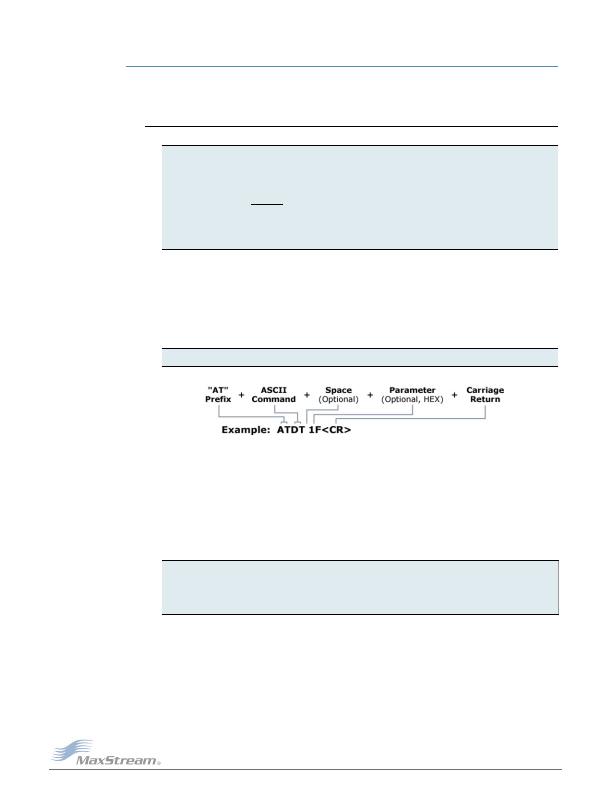
To Send AT Commands:
Figure?08.燬yntax爁or爏ending燗T燙ommands?/DIV>
To read a parameter value stored in the module register, leave the parameter field blank.
The preceding example would change the modules Destination Address to "0x1F". To store the
new value to non-volatile (long term) memory, the Write (ATWR) command must subsequently be
sent before powering off the module.
System Response. When a command is sent to the module, the module will parse and execute
the command. Upon successful execution of a command, the module returns an
OK
message. If
execution of a command results in an error, the module returns an
ERROR
message.
To Exit AT Command Mode:
For an example of programming the RF module using AT Commands and descriptions of each config-
urable parameter, refer to the "RF Module Configuration" chapter.
1. Send the 3-character command sequence "+++" and observe guard times before and after
the command characters. [refer to Default AT Command Mode Sequence below.] The Ter-
minal tab (or other serial communications software) of the X-CTU Software can be used to
enter the sequence.
[OR]
2. Assert (low) the CONFIG
pin and turn the power going to the RF modem off and back on. To
achieve this result, simultaneously press the Reset and Config switches [Figure 1-02];
release the Reset Switch; then after 1 second, release the Config Switch. The RF Modem
then enters AT Command Mode at the modem's default baud rate
Send AT commands and parameters using the syntax shown below.
1. If no valid AT Commands are received within the time specified by CT (Command Mode
Timeout) Command, the module automatically returns to Idle Mode.
[OR]
2. Send ATCN (Exit Command Mode) Command.
发布紧急采购,3分钟左右您将得到回复。
相关PDF资料
ZMN2400HPDB
BOARD ROUTER DEV ZIGBEE 100MW
ZMN24HPDK-B
KIT DEV W/ZIGBEE ZMN2400HP
ZNI1000TC
IC TEMP SENSOR NI1000 SOT23-3
02110102-000
SNSR TILT RATIO 60DEG 500MA FLNG
1-5209285-2
FOPC BOA 12DB FC/UPC BP SM
2-1693560-0
BOA 20DB LC/UPC BB
517SS16
MAGNETIC SENSORS BIPOLAR ICS
5209597-9
BOA 9DB DW SC/APC
相关代理商/技术参数
XIB-U
功能描述:界面模块 USB interface board 24XStream 9XCite
RoHS:否 制造商:4D Systems 产品:Serial Converters 通道/端口数量: 数据速率: 接口类型:USB, UART 工作电源电压:3.3 V, 5 V 最大工作温度:
XIC25040
制造商:XIC 功能描述:25040 24HR '6
XILINXPWR-079
功能描述:电源管理IC开发工具 Pow Mgt Eval Mod for Xilinx FPGAs RoHS:否 制造商:Maxim Integrated 产品:Evaluation Kits 类型:Battery Management 工具用于评估:MAX17710GB 输入电压: 输出电压:1.8 V
XILINXPWR-080
功能描述:电源管理IC开发工具 Pow Mgt Eval Mod for Xilinx FPGAs RoHS:否 制造商:Maxim Integrated 产品:Evaluation Kits 类型:Battery Management 工具用于评估:MAX17710GB 输入电压: 输出电压:1.8 V
XILINXPWR-081
功能描述:电源管理IC开发工具 Pwr Mgmt Eval Mod Xilinx RoHS:否 制造商:Maxim Integrated 产品:Evaluation Kits 类型:Battery Management 工具用于评估:MAX17710GB 输入电压: 输出电压:1.8 V
XILINXPWR-082
功能描述:电源管理IC开发工具 Pow Mgt Eval Mod for Xilinx FPGAs RoHS:否 制造商:Maxim Integrated 产品:Evaluation Kits 类型:Battery Management 工具用于评估:MAX17710GB 输入电压: 输出电压:1.8 V
XILINXPWR-083
功能描述:电源管理IC开发工具 Pwr Mgmt Eval Mod Xilinx RoHS:否 制造商:Maxim Integrated 产品:Evaluation Kits 类型:Battery Management 工具用于评估:MAX17710GB 输入电压: 输出电压:1.8 V
XIM15120-G-C2E
制造商:Thomas & Betts 功能描述:INCANDESCENT